Development of custom electronic boards with CNC Router.
As a Fablab Peru team, we have decided to embark on the exciting task of building a 3D machine capable of printing personalized cookies using emblematic ingredients from our region, such as "MACA", a product originating in Peru. This project represents a unique combination of technological innovation and promotion of our local products, highlighting the richness and diversity of our culinary culture. We are excited to create a personalized and authentic culinary experience that celebrates our Peruvian heritage while exploring the limits of digital manufacturing applied to gastronomy. We hope this initiative inspires others to experiment with the fusion between technology and tradition in the food field!
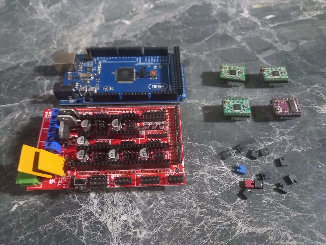
Having defined the machine, the crucial moment arrived to select the hardware that will give life to our project. This step is essential, since the appropriate choice of components will determine the performance, reliability and efficiency of our machine. We are committed to opting for quality hardware that meets our technical specifications and ensures optimal performance over time.
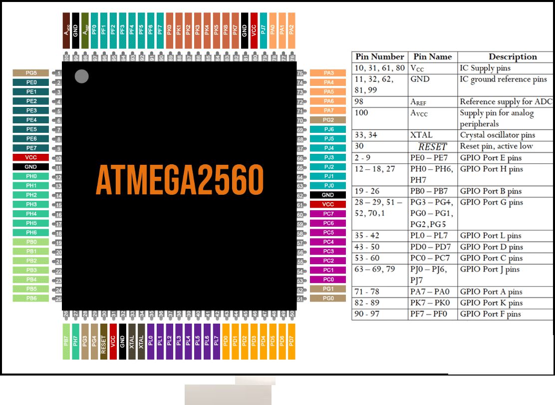
We are considering two microcontroller options for our machine, based on their capacity and layout. This decision is crucial to ensure efficient and reliable operation. We are carefully evaluating both options before making a final decision.
Features and Specifications
RAMPS 1.4 is probably the most widely used electronics for RepRap machines as of March 2014. It consists of a RAMPS 1.4 shield, an Arduino Mega 2560 board (or a clone), and a max of five Pololu Stepper drivers. It can control up to 5 stepper motors with 1/16 stepping precision and interface with a hotend, a heatbed, a fan (or a second hotend), a LCD controller, a 12V (or 24V with appropriate modification) power supply, up to three thermistors, and up to six end stoppers.
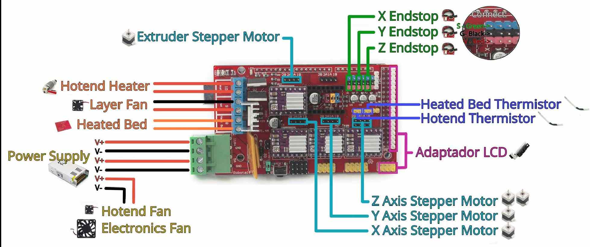
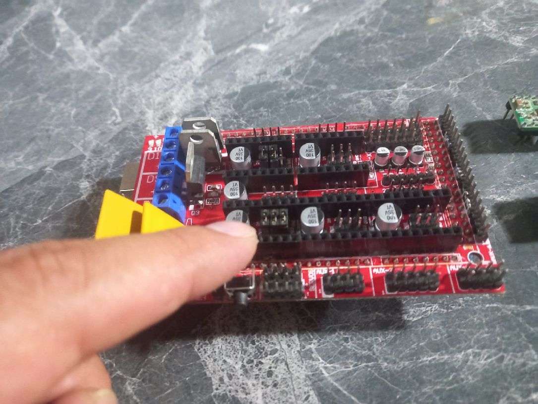
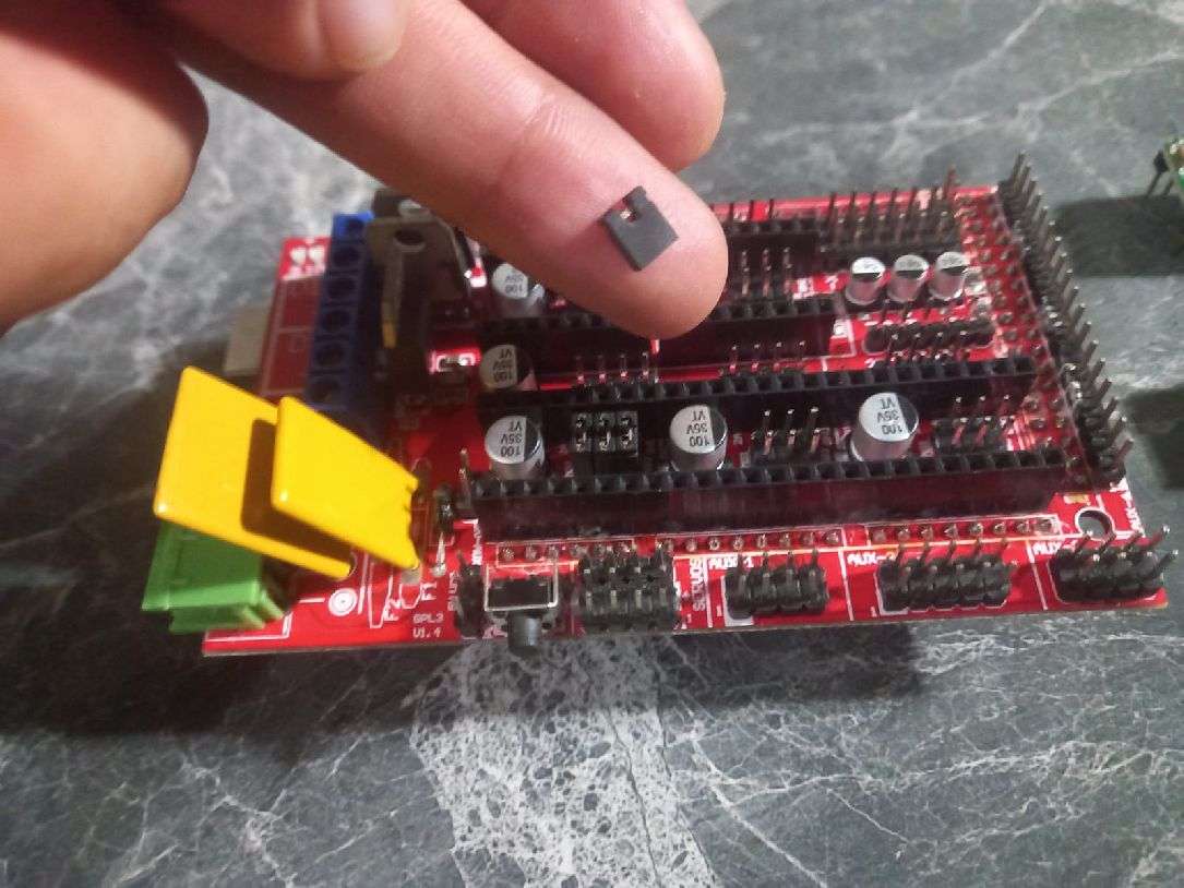
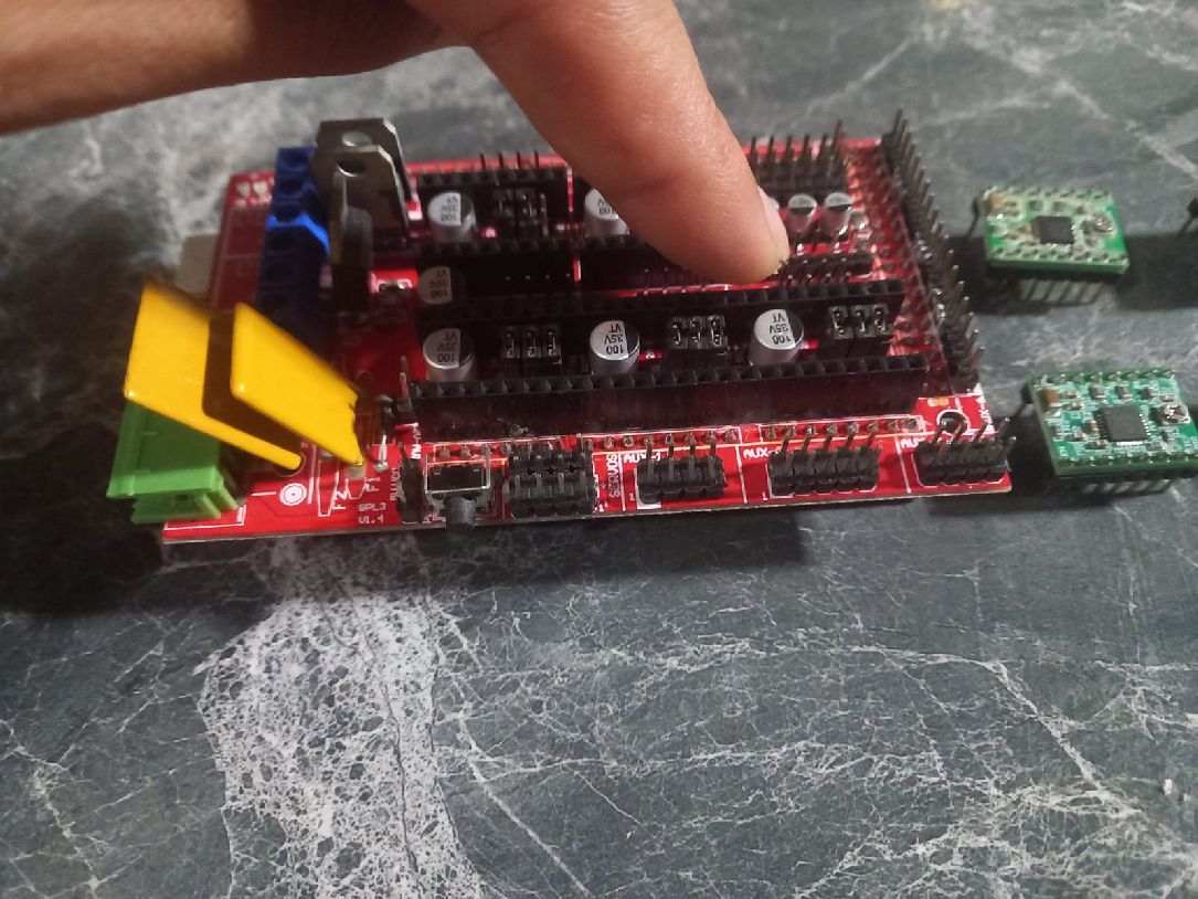
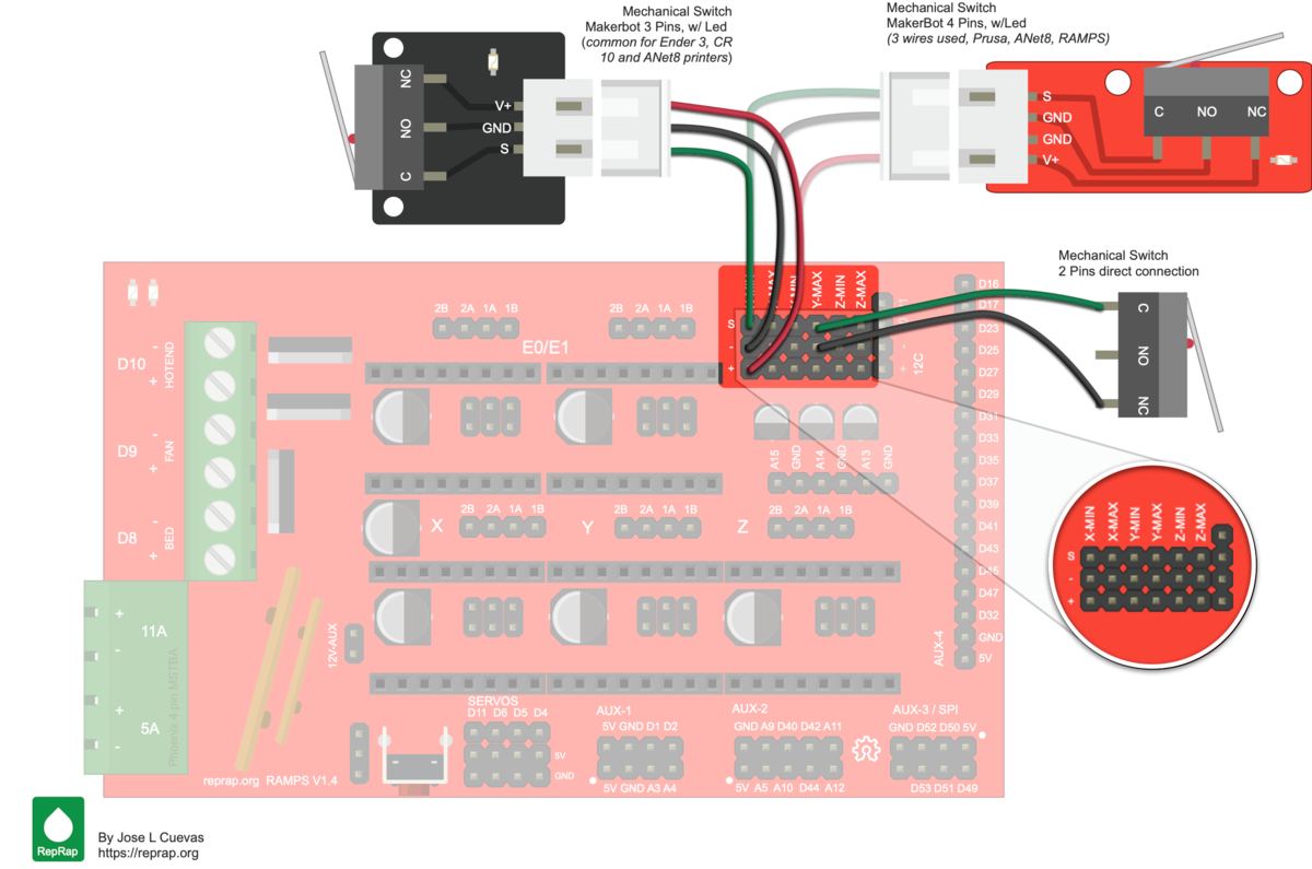
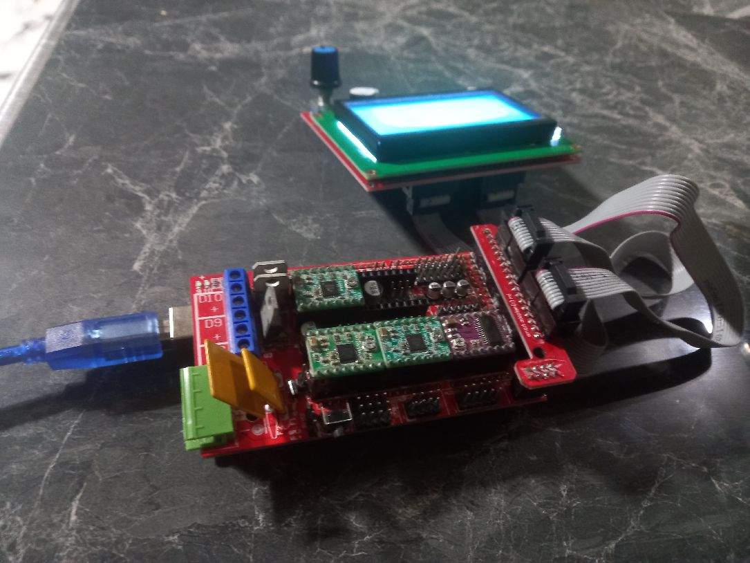
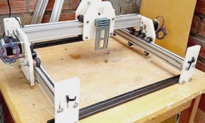
With the Ramps 1.4 board in our hands and the necessary components ready, it is time to proceed with its installation following both the image provided and the detailed instructions on the website.
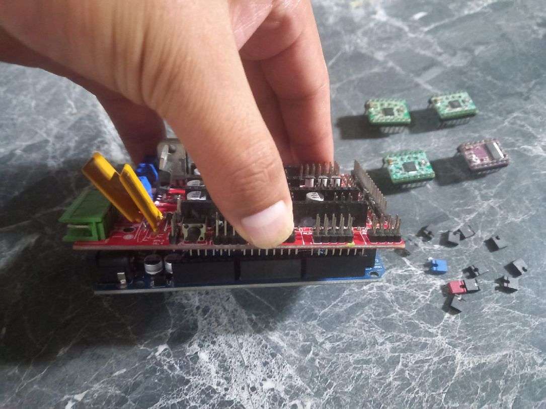
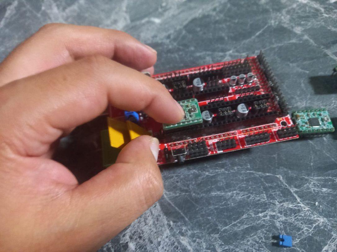
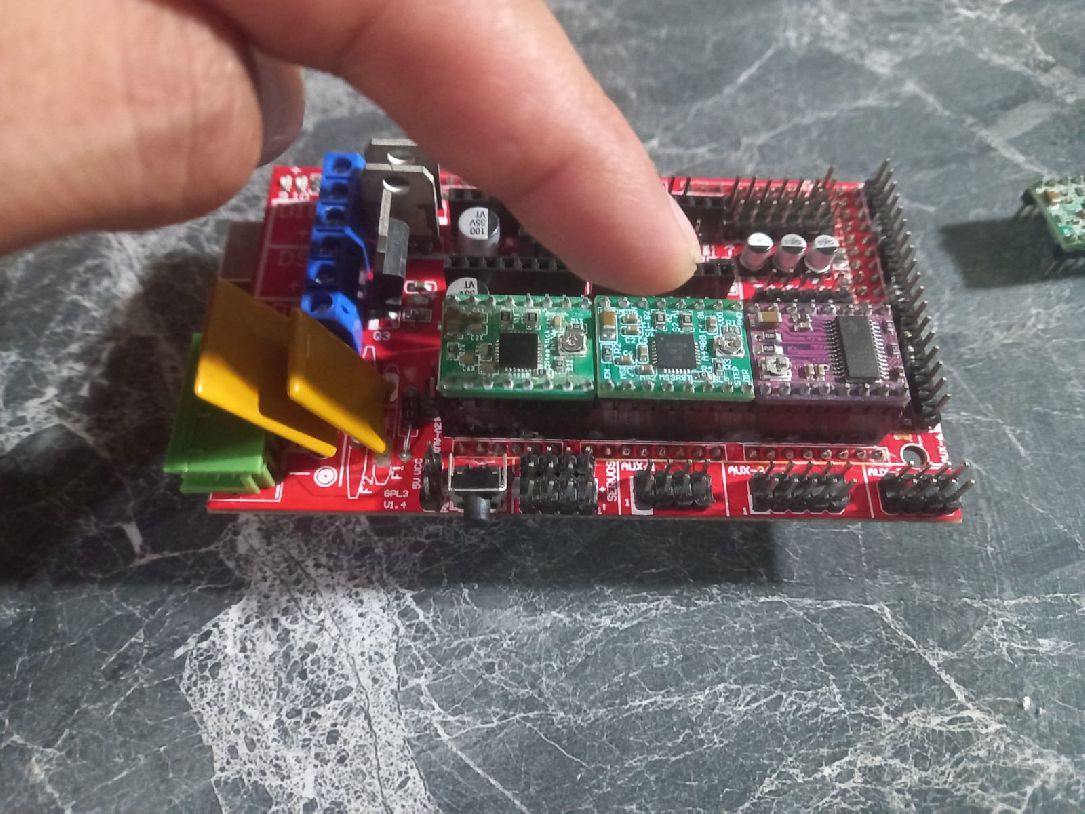
We place all the components, such as the jumpers, as shown in the image, with three of them on each motor driver. This configuration is done to improve the resolution of the engine.
The image provides the guide to correctly place the limit switches of the 3 axes.
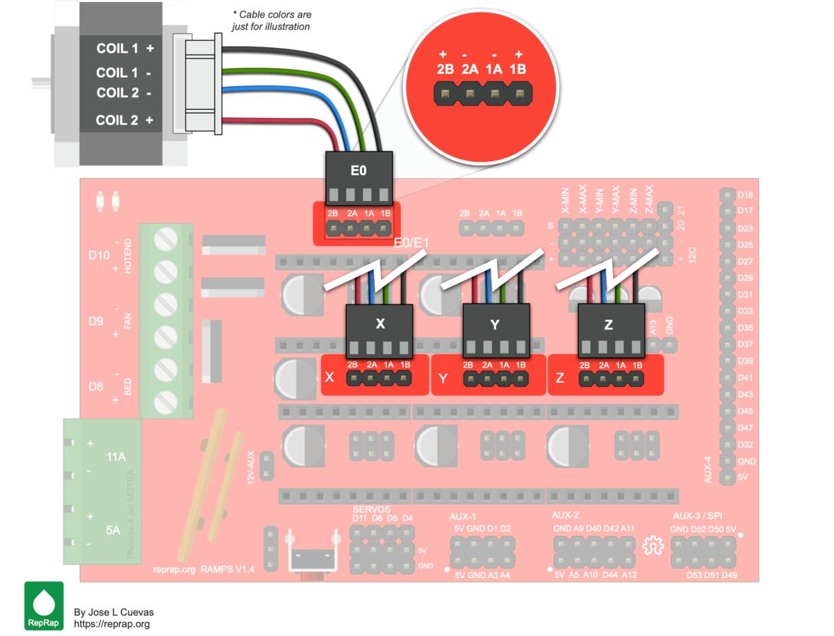
The following image shows the correct placement of the Pololu A4988 drivers. It is crucial to follow this guide in detail, since the wrong direction can irreparably damage the drivers.
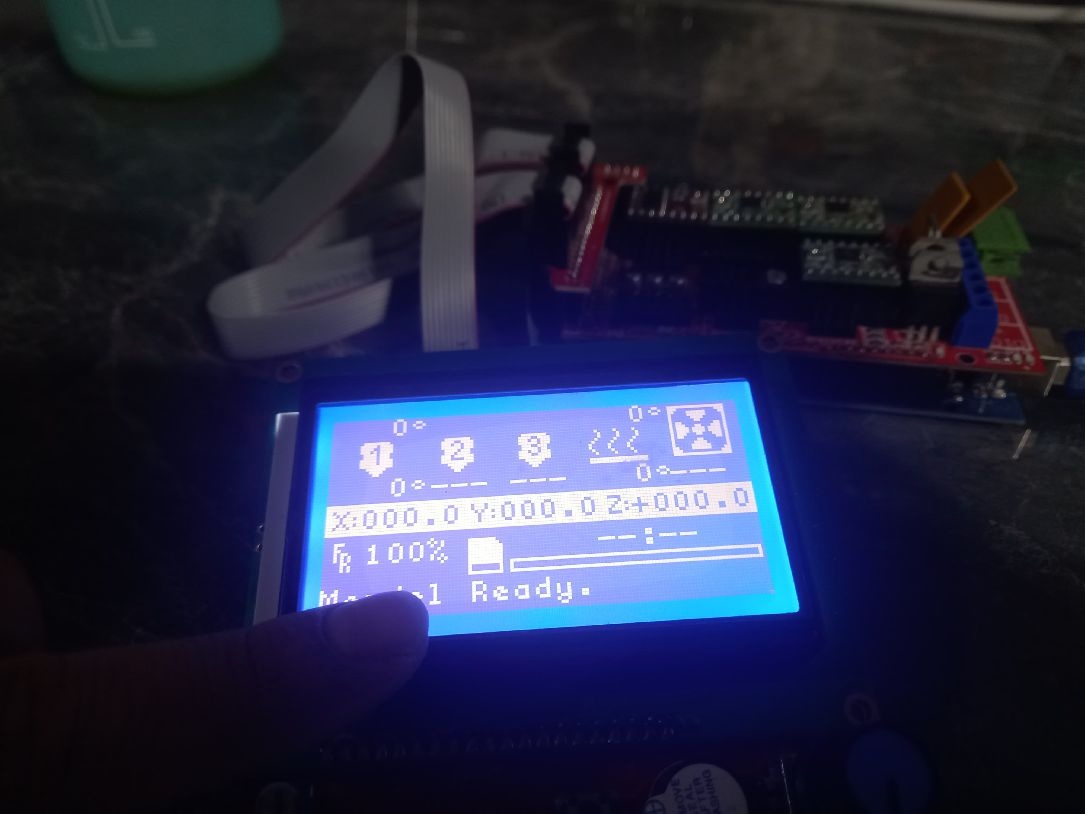
The following image illustrates the correct placement of the graphic LCD. It is extremely important to follow these settings to ensure proper operation.
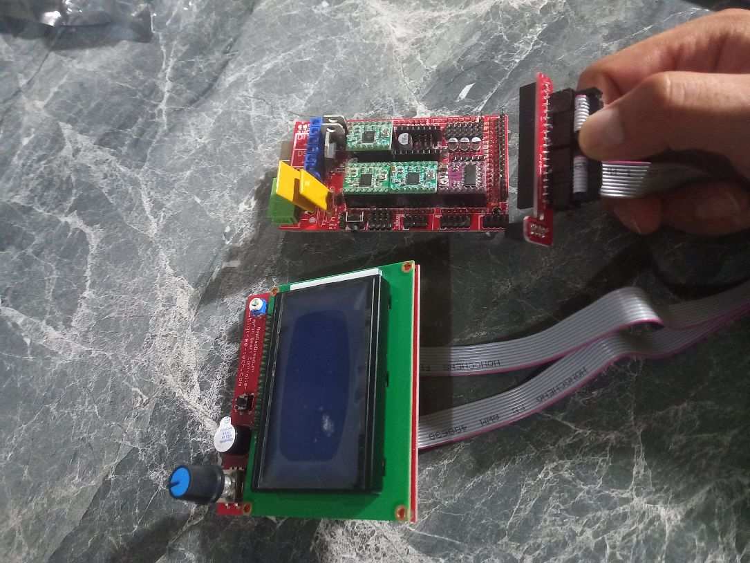
The following image confirms that our LCD is operational and presents the correct way to position the extruder motor. It is essential to follow these instructions for optimal system operation.
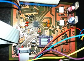
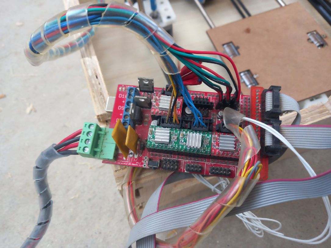
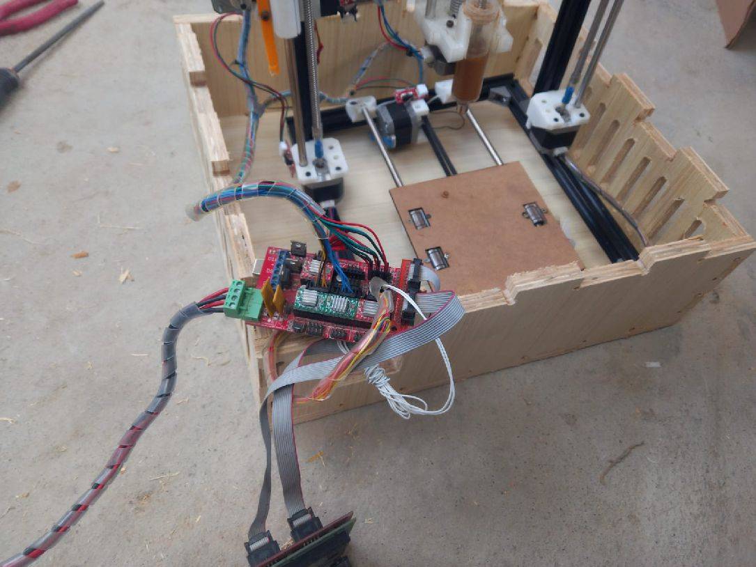
The next step is to place the electronics inside the box specially designed for the machine, firmly securing all the connectors.
Calibration is a critical stage of machine setup as it determines whether it will work correctly or not. It is crucial to devote time and attention to this process to ensure optimal performance.
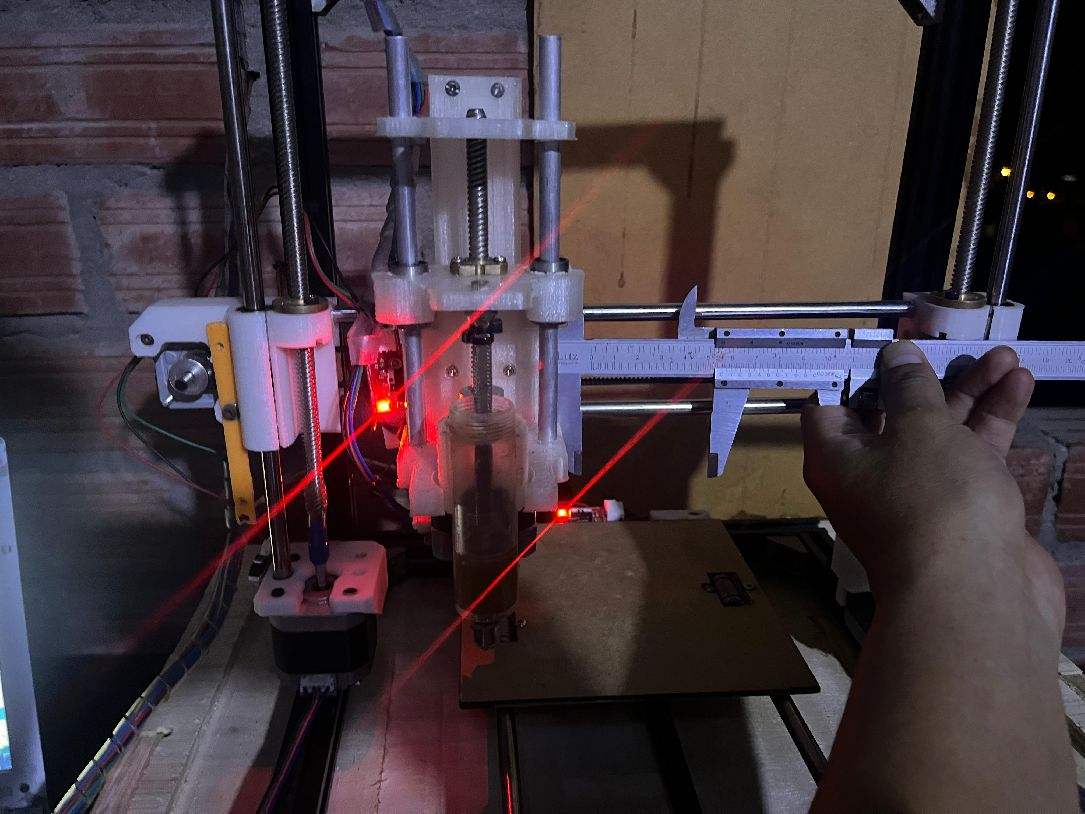
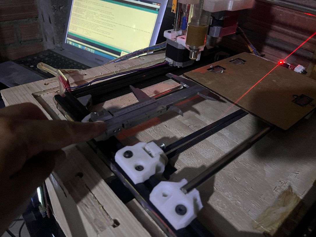
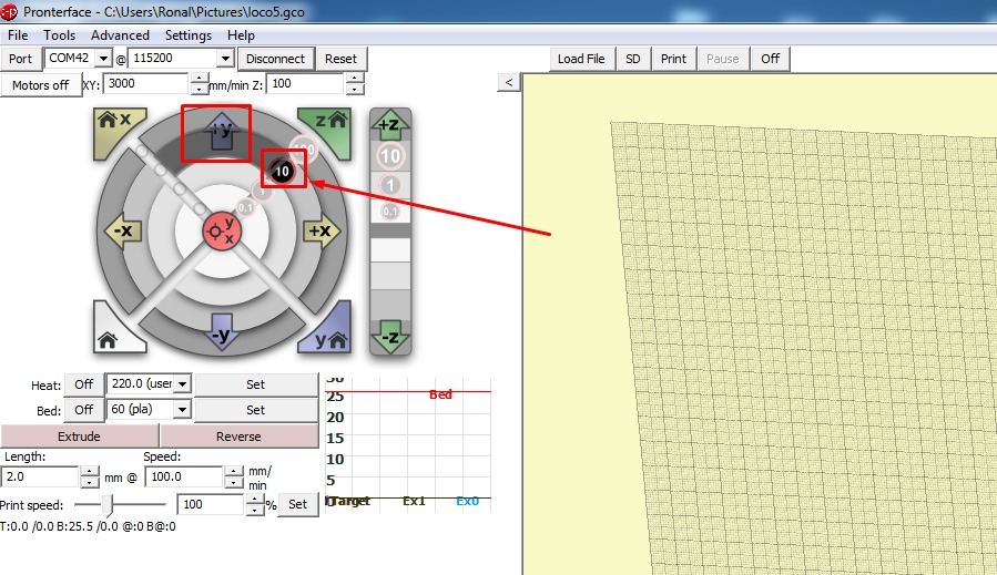
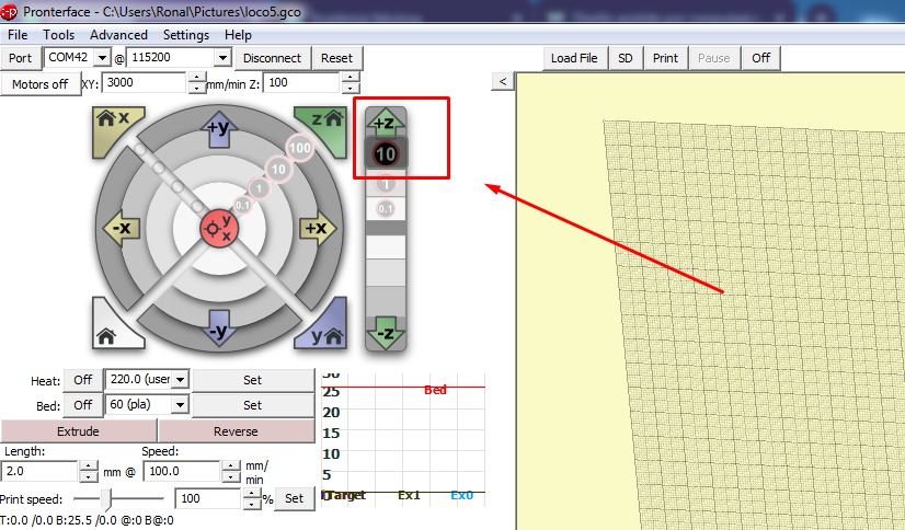
The following image shows the process of measuring the displacement on the X axis using the Bernier tool. The procedure is as follows: we place the Bernier on the X axis and then, in the Pronterface software, we indicate a displacement of 10 mm. The machine will move and we will take this measurement to perform the corresponding steps per millimeter calculations in the software.
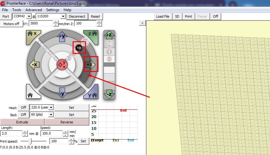
Similarly, the next step involves measuring the displacement on the Y axis using the Bernier tool. We place the Bernier on the Y axis and, through the Pronterface software, we indicate a displacement of 10 mm. The machine will move and we will record this measurement to carry out the necessary steps per millimeter calculations in the software.
If you got a value of 100.63 steps per millimeter when measuring the displacement with the Bernier tool, and you are using 21-tooth GT2 pulleys and a GT2 belt, then this value is effective for your setup.
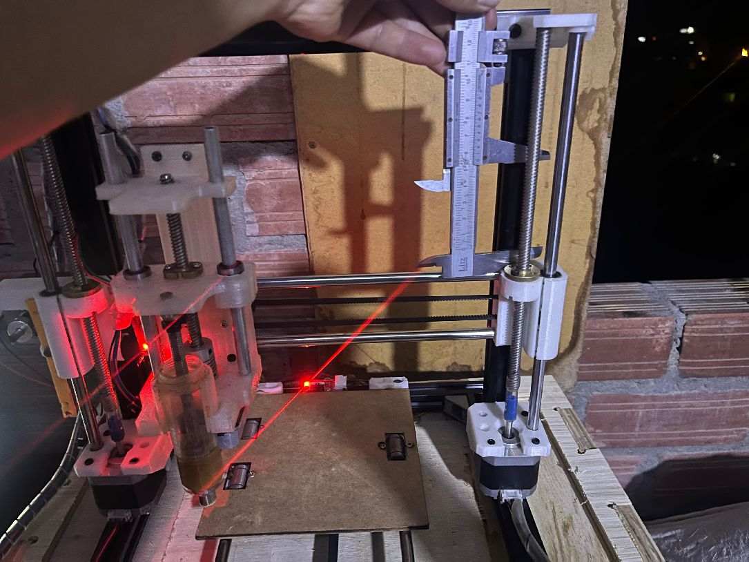
The following image shows the process of measuring the displacement in the Z axis using the Bernier tool. The procedure is similar to that of the X and Y axes: we place the Bernier on the Z axis and, using the Pronterface software, we indicate a displacement of 10 mm. The machine will move and we will record this measurement to perform the respective calculations of steps per millimeter, taking into account that we are using an M8 Spindle and two NEMA 17 0.7 amp motors.
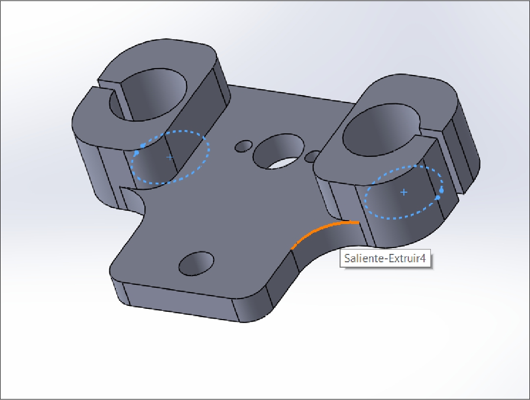
All of the parts I will present below were meticulously designed using SolidWorks, as illustrated in the image below, allowing us to guarantee precision and quality in each component of our project.
Intermediate GUI that makes it easy to move the machine's extruder.
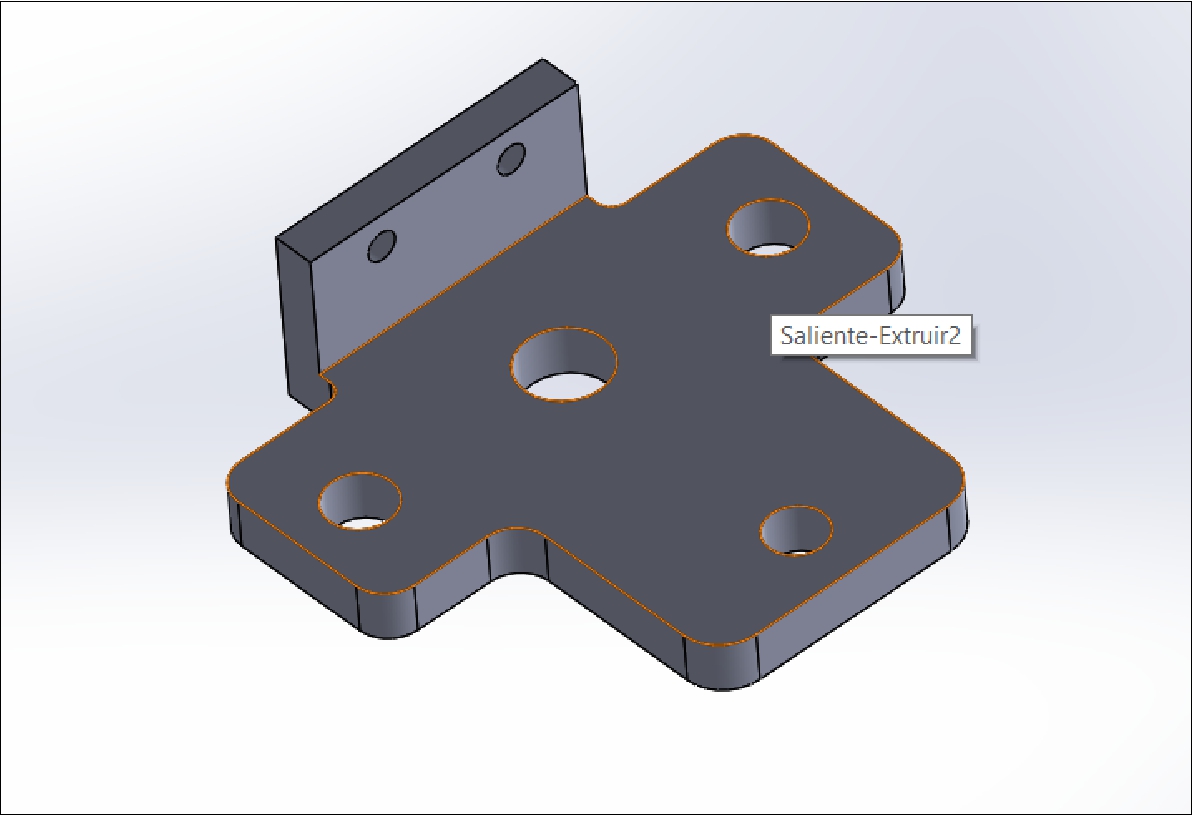
Upper guide that provides stability and precise positioning of the rods.
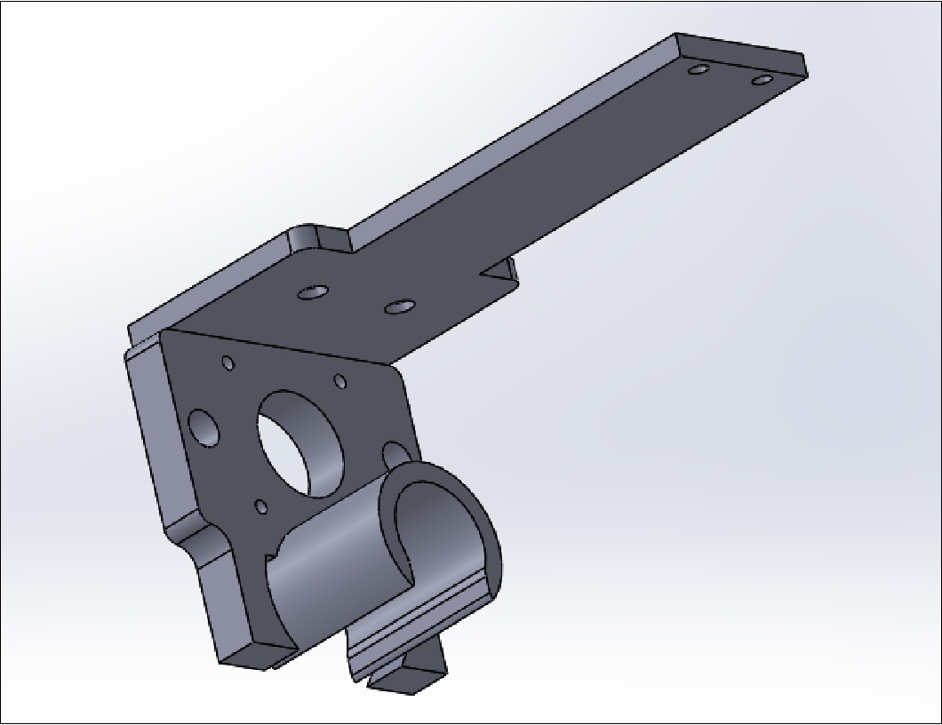
Main support that is placed on the 'X' rail, where all the pieces converge to form the extruder.
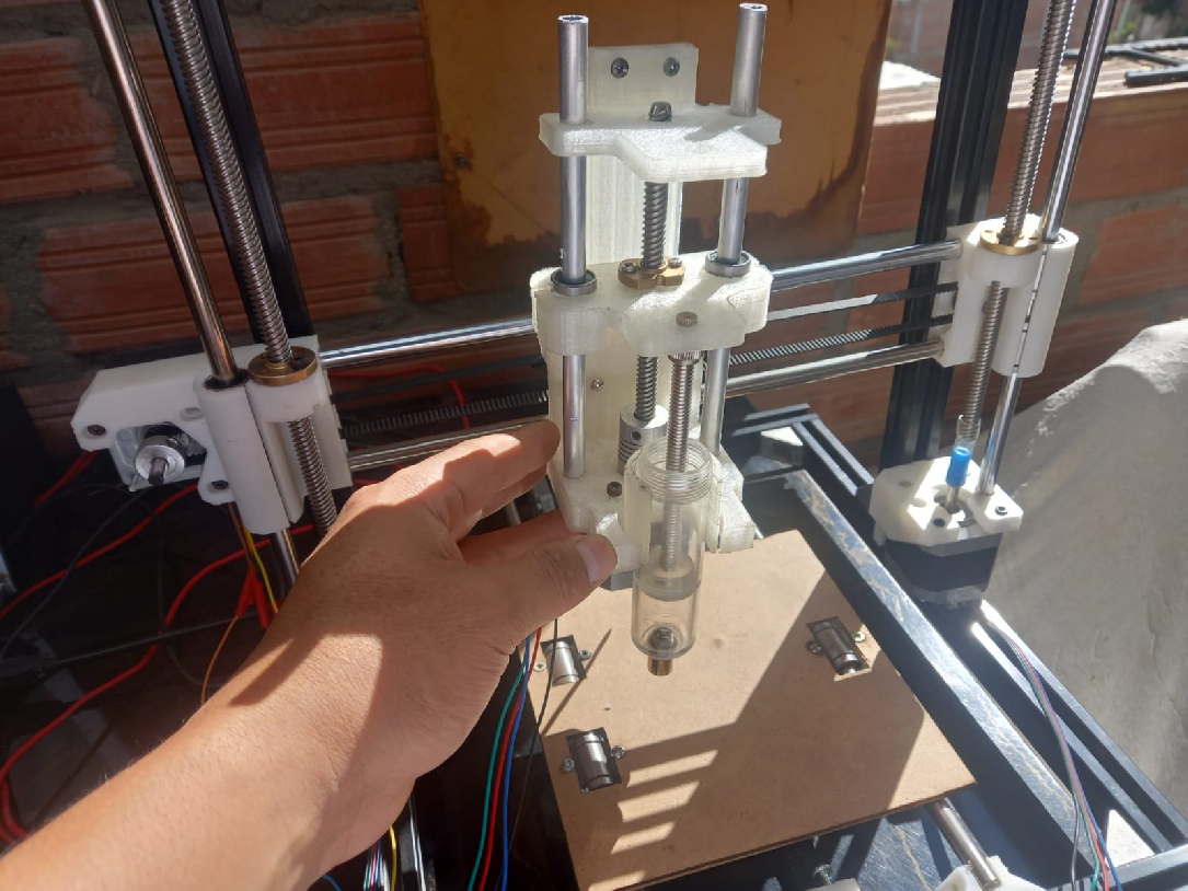
In the next step, we will print the parts using our 3D printer. Subsequently, we will proceed with the assembly of the injection system, which will allow us to visualize the complete operation of our project in action.
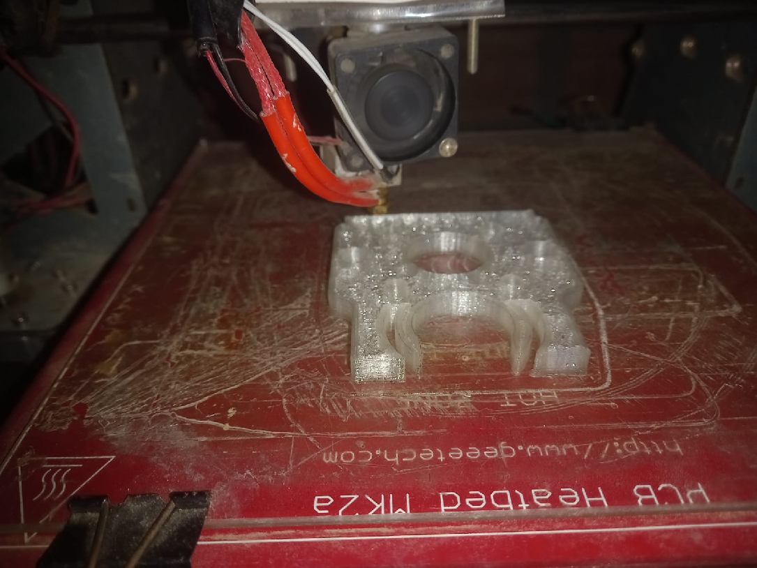
Printing the extruder parts
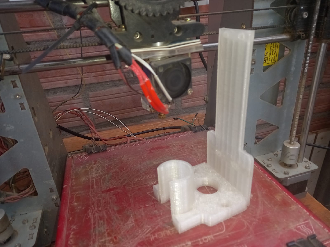
Printed upper, temple stabilizer
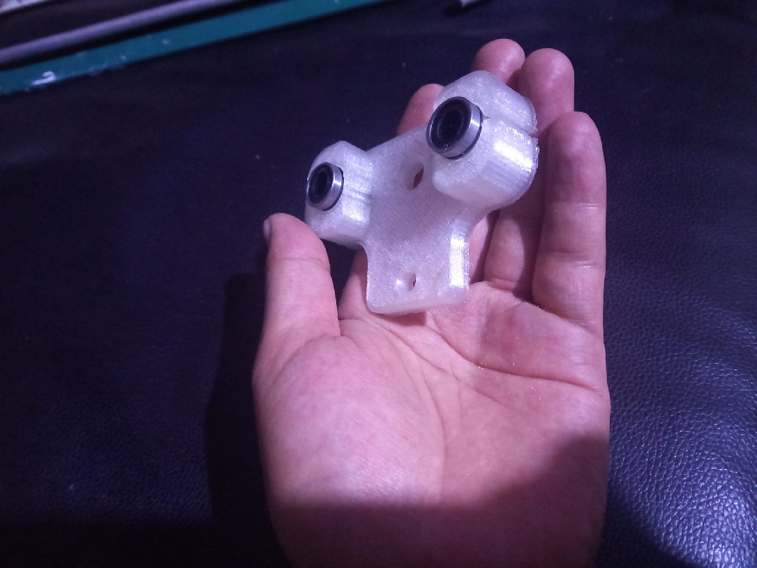
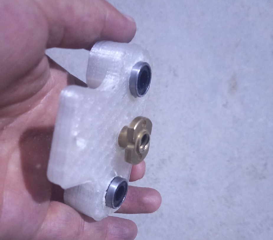
The central shaft assembly facilitates extruder dosing. The first image shows the insertion of the linear bearings, and in the next image on the right is the tee that allows the movements to be precisely calibrated.
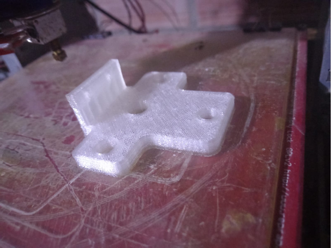
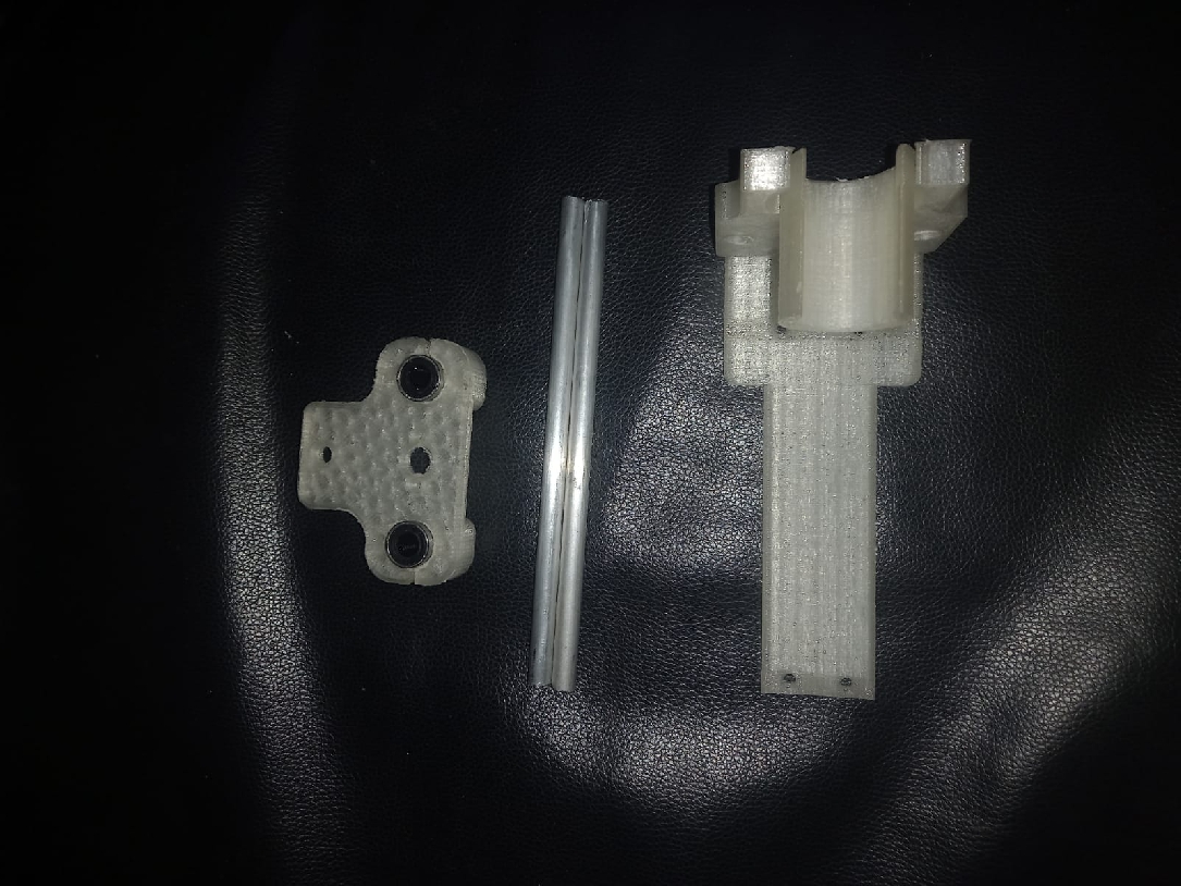
In the following image you can see the final result of the printing of the main extruder support, as well as the parts necessary to begin assembling it and perform the first tests.
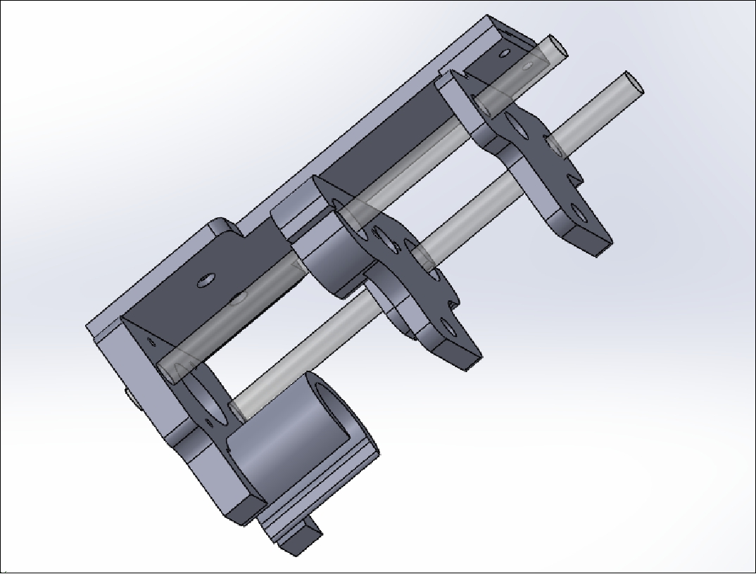
Extruder assembly process with M8 aluminum rods. This material was chosen due to its lightness, which is essential to reduce the weight of the extruder.
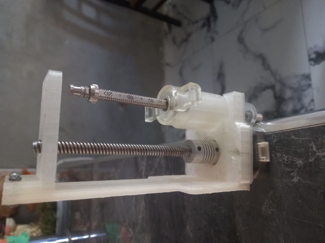
In the following image you can see that the assembly process is complete and ready for the first tests.
This week has been extremely enriching in terms of learning. I had never ventured into building a machine with liquids before, and I must say that the result has been excellent. Collaborative teamwork was essential; Each member contributed from their experience and knowledge, which allowed collective learning. I am excited to continue doing more experiments with polymer prints and continue improving this machine in the future.
Development of custom electronic boards with CNC Router.
Development of personalized keychains and ornaments with CNC Laser.
Development of custom machines "Desktop CNC Laser.

Huánuco is a Peruvian city, capital of the district, province and department of the same name in the north-central area of the country. The city has a population of 235,529 inhabitants. .